Note: One recommends reading the diary first and then linking to workshop notes to maintain the continuity of the theme...
1
2
Ign.Switch Panel
Start Switch
WebCam Back
Radio 2
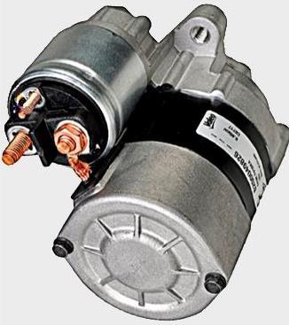
Battery Cut-Off
Dash USB-1
A/C Fan - A
Radio 1
Exhaust Cut-Off
Running-Lights C
USB Hub
USB Dash-2
USB Console Bck
USB Console Frt
Accessory
Accessory
Accessory
Accessory
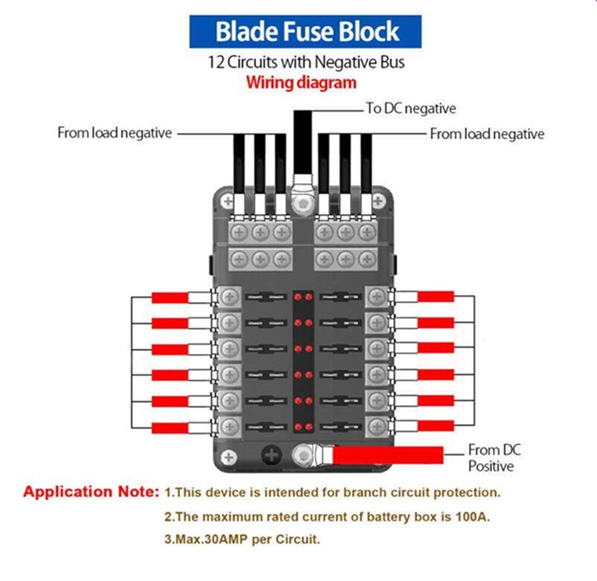
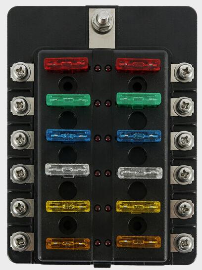
Fusebox 2 Ignition Supply
Fusebox 1 - Direct Battery Supply
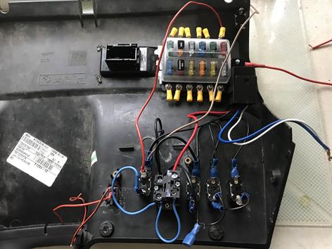
Rear Panel Wiring
1
Jumpers
Covering:
Fuel Cut-Off
WebCam Front B
illuminates
for LED
common Ground
Direct Battery Current
3 Post Switch
Note::
Note:
Note: Slightly Different Fusebox - No earth points earth will be on the accessory
Over All Circuit
Bulb/earth
This wire layout allows the LED in the switch to illuminate on the up-stroke of the switch
WebCam
Jumpers
A
B
C
Ground/earth
White Switch Ignition
Blue Starter/Ignition
Black earth/Ground
C
1st & 2nd Switch Position
To Switch Panel
A/C Fan
Running Lights
This is the one I am going with and it just leaves installing into the vehicle
Noting: The remaining wiring of two wires the Blue and White to the ignition switch hub under the steering column and obviously the positives to the accessories and ground
Batt
Fuse & Box
Relay
Push Button Start
Batt Supply
WebCam
A/C Fan
Running Lights
Ignition Switch
Jumpers
Jumpers
Jumpers
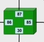
86
30
85
87
C
Accessorites
Ground
Push/Start Switch Panel with Relay and Fusebox Circuit Diagram
Spare
To Battery or Live Supply
To Ignition Switch on Steering Column
End Terminal to Chassis Ground
Not Used
Final Wiring
Positives toAccessories
Hopefully this will help someone out, as complete notes & videos online do not fully explain or at times they leave out some part of importance. I have watched many videos and most times the host's ego's can get in the way or they fail to get their point across clearly. However; they do mean well, only one does need to get the job done. As egos goes, I think everything has been covered, let me know if my effort has failed to get across. ;)
Note: I have not added all of accessories to the fusebox or to the switches for obvious reasons, as the dash panel needs to be reinstalled onto the vehicle first, for routing, connect/wire to the appropriate already installed accessories. Hence the non-wired, yellow unused coloured wire connectors on the fusebox and not forgetting the switch 'positives' also need their connections on the three dash switches to their appropriate accessory.