Note: One recommends reading the diary first and then linking to workshop notes to maintain the continuity of the theme...
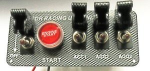
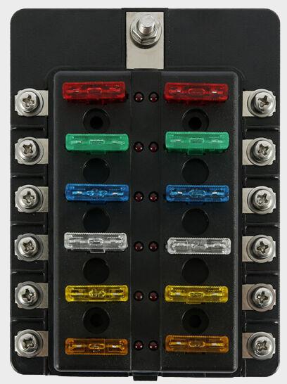
This is the switch combination I have decided on. This leaves 4 switches from the original delivery set up. I also have the fuse box Why the change? I preferred the switches to all illuminate on the panel and all to have covers, as to not to accidently switch them off during getting in and out of the vehicle, that is if it is possible with my setup? The covers also provides further protection to the push-start button. So! One can say there are a combination of reasons for the changes. Instead of using one fuse box internally, there will be two, these will be repositioned to a new location under the dash. Fusebox 1, will be a direct circuit to Battery and 2, will be a live circuit from the Ignition circuit.
1
2
Ign.Switch Panel
Start Switch
WebCam Back
Radio 2
Battery Cut-Off
Dash USB-1
A/C Fan - A
Radio 1
Exhaust Cut-Off
Running-Lights C
USB Hub
USB Dash-2
USB Console Bck
USB Console Frt
Accessory
Accessory
Accessory
Accessory
Fusebox 2 Ignition Supply
Fusebox 1 - Direct Battery Supply
Switch Designation
These two additional switches will be hidden adding to more security of the vehicle. They will not need to be illuminated.
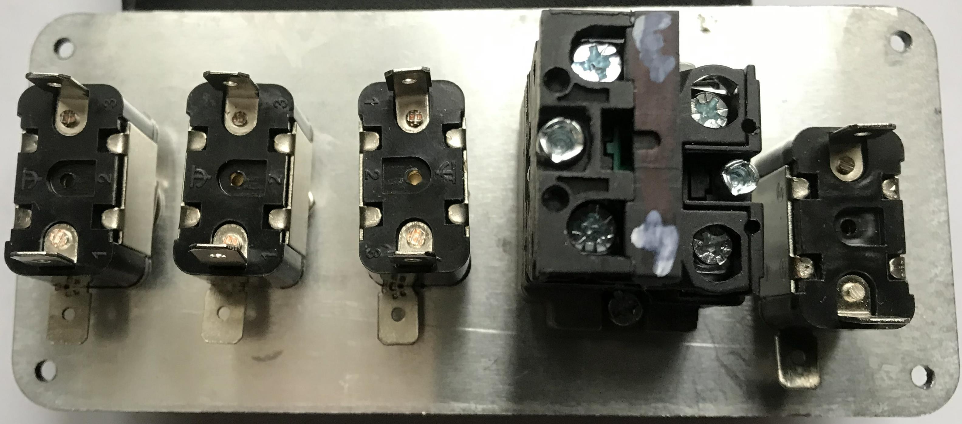
Rear Panel Wiring
Switch Bulb Ground/earth
Positive to Accessory
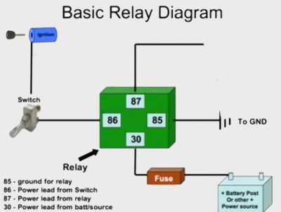
Relay Connections
C
C
C
Situated on Steering Column
1
Ignition Switch Panel
Start Switch
WebCam Front B
WebCam Rear
Radio 2
Battery Cut-Off
Dash USB-1
A/C Fan A
Jumper
Jumpers
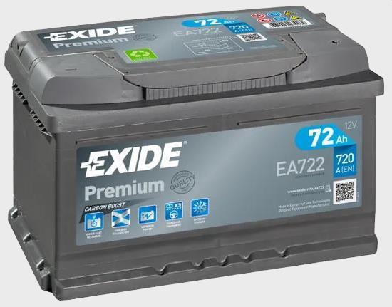
Car Battery
Negative Earth to Car Chassis or Battery
A
B
C
To Second Fuse Box
Direct Positve
Covering:
Fuel Cut-Off
A/C Fan A
WebCam Front B
Running Lights C
Battery Cut-Off D
Fuel Cut-Off E
Fuel Cut-Off
WebCam Front B
There are many out there like me, having little to no experience of wiring cars and from time to time; one comes across incomplete information from varied sources that just doesn't help. As for me, I am not an electrician by trade and therefore get by just!... So there is a need to find good and reliable sources on one's particular topic; this is unfortunately rare. However, a combination of information collectively can help to place the pieces together, so one needs to do a study. One will need to work out a diagram of sorts to the best of one's ability to fulfil one's needs. So this is my effort and new plan:
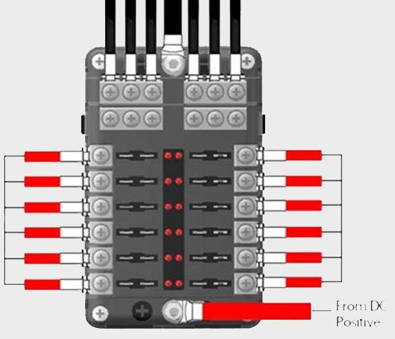
To make this less complicated I will just deal with the Push Start Panel and two of the switches that will go directly to Fusebox 1, (Direct Battery Current) as indicated above and the panel below. (Note: Switches and Relays can be different, hopefully your setup is like the one described)...
illuminates
for LED
common Ground
Direct Battery Current
3 Post Switch
2 Post Switches
Note::
Note:
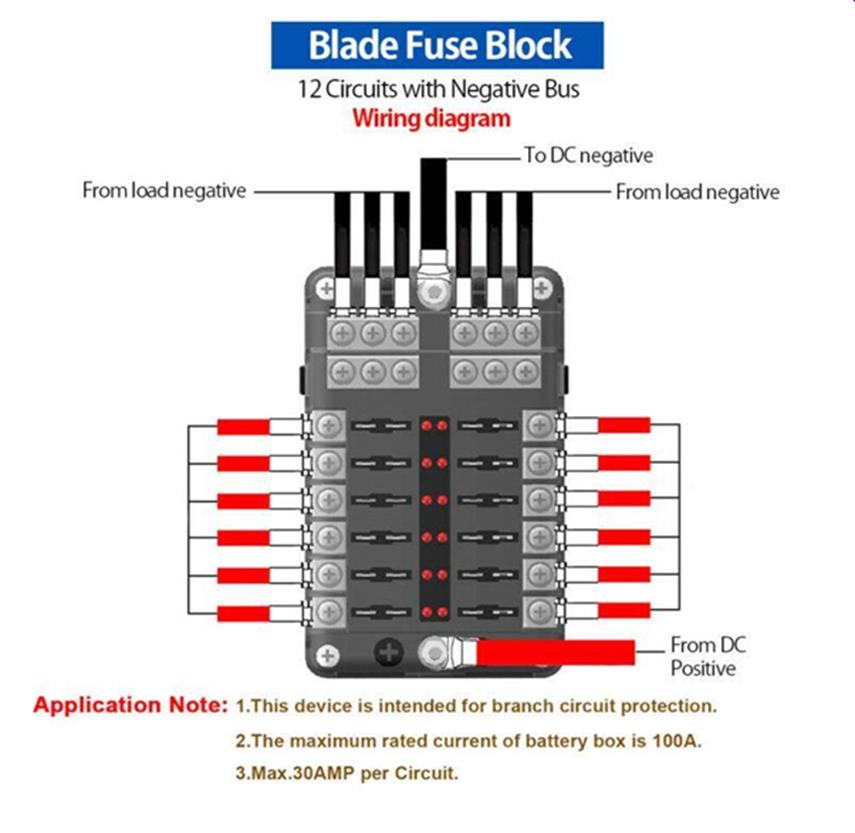
Note: Slightly Different Fusebox - No earth points earth will be on the accessory
This Circuit will work, however there will be changes to the switch poarities
(For Larger Final Diagram)>>>
See Video on Next Page for Install Instruction: Video