Note: One recommends reading the diary first and then linking to workshop notes to maintain the continuity of the theme...
Dash Presentation - After long deliberation, the back panel just did not appeal to me, this was down to the aesthetics of it. I did place the panel into position with the switches, as the holes had already been drilled. My mind was made up after trying to get the switch nuts on with the panel in place, there seemed to be a problem with the thickness or depth of the switch panel and dash facia thickness. So this really prevented me from having enough thread to attach the switch retainer nuts for mounting the switches onto the dash. This really made my mind up for me....I would do without the panel.
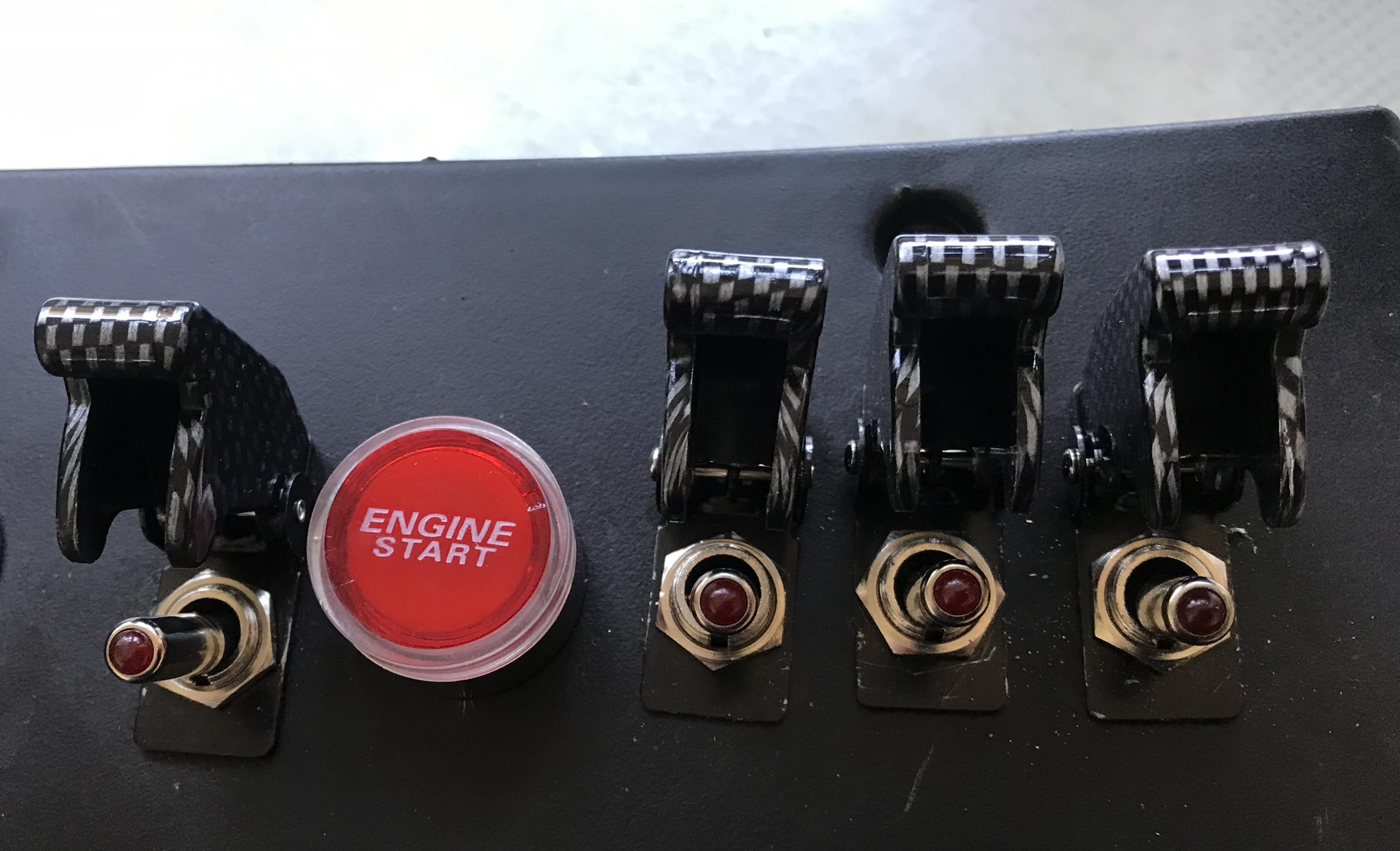
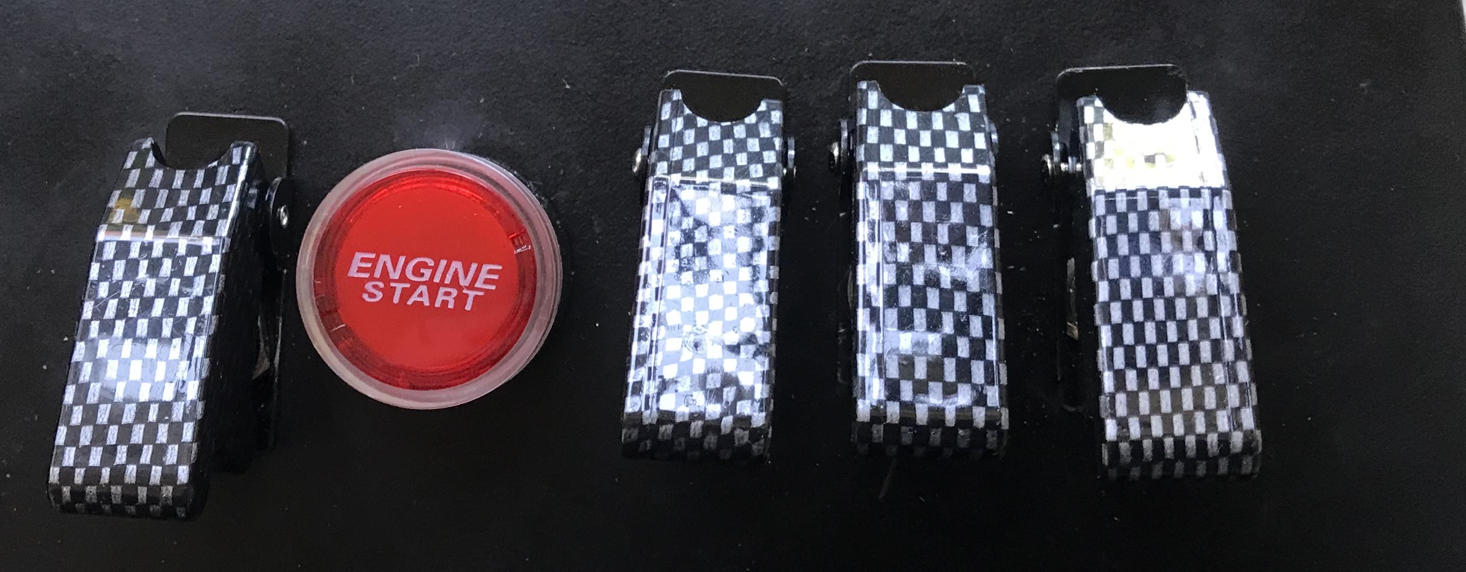
One must also consider in this image, one is looking directly onto the switches bearing in mind these will be facing further down from the drivers direction of sight, when the facia is returned to it's proper position, hopefully the switches will look correct... As to the illumination, one will no doubt see it at night and if a problem arises, one can manipulate oneself to see if any of the LED's are out and investigate.
Not sure if the switch covers are all of uniform size looking at this image - the drilled holes were all correct and at the correct heights of line up - The back plate or panel was used as the template for the holes bearing in mind, the ignition switch was also offset to begin with - perhaps they just need straightening or it is an optical illusion, hopefully! However, this will not be noticed too much when all is put back in it's proper location? Yes! I am an optimist ...
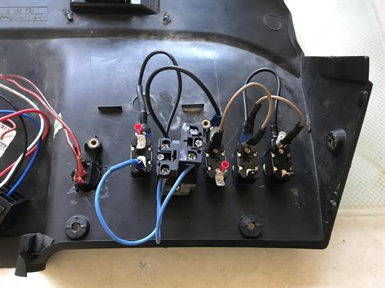
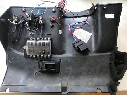
Now for the wiring: I have placed a number of double spade connectors onto the terminals, mainly down to running very low on single spades and crimping failures, some will know what I'm talking about.... All the earth/ground connection has now being bridged, (Black & BMW Brown Wires are the negative/ground). The Neutrals or jumper wires are coloured Blue, this just leaves the Red (Live/Positive wires) to be connected. The Relay can also be added, just waiting on a new delivery of wire and of course the additional small internal fusebox; it is progressing...
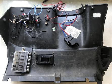
I am hoping there will be enough room to mount the new fusebox here?
curve
Failing this, a plate may be required to attach to the firewall to mount the fusebox or it could be located within the centre console? Just thinking out loud....!
?
?
June 2022 project currently in Progress
The Fusebox has now arrived delivered, (21.02.22) slightly different to my other fusebox as it doesn't have the negative or earth posts, however this is not really a problem as long as the attached accessory has an earth post attached to itself or it is in itself a ground unit via the body or chassis.
There are a couple of locations, possibly?
? Location 1
? Location 2
Note: The relay still needs to be attached
We can now revisit where the fuse-box can be located
slight ridge is do-able
Again, not perfectly flat, Is do-able
As mentioned before, there is always the location of going under the centre console. One must remember the task of having to relocate the wiring and routing the wires, to a point of being able to gain access, mainly to change the fuses if and when required. Decisions, decisions....
23.06.22 - Over the past few days, I have been fighting a non-working circuit for my switches, as well as this there has been problems unfortunately, with some imported sub and inferior electrical products and as many of us fall for the cheap; we start an ever decreasing circle. They are cheap for a reason! Don't get me wrong, there are some good product out there, however far and few between it seems and even there are those with less the appropriate instructions. I have changed the circuit a little and it is down to the process of elimination. I will add the circuit layout work as and when. I am also hoping that you can see my thinking process and perhaps learn from my mistakes to save time with this type of installation. Continue to the last page in this project 26-26c for a working circuit.
I have so far, established the location for the switches and fuse box, worked out the wiring of the relay and now establishing the functionality of the switches, i.e. with 'ON' being up on the switch to make them all uniform- ended up with the following: (See next page).....
The next task was to get it all to work together from the fuse box, to switches via the relay to the accessory, well in theory at least. The final test will be on installing it all into the vehicle and playing around with the accessories from the other fuse box, remembering fuse box 1 was for Direct Current from the Battery and the other fuse box, was to function via the Ignition positive, in other words; as to only allow the accessory to work during the time the key is within the Ignition system.