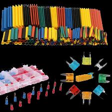
Material Requirements: 1 x Switch x Wire x Insulation Tape &/or Heat Wrap x Spare 15A Spade Fuses x Male/Female Terminal Spade Connectors x Separate Fuse Terminal x Plastic corrugated tubing for wiring
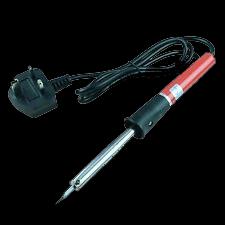
Tools: x Ratchet Set with Sockets and Star Drivers x Wire Cutters x Soldering Iron & Solder x Drill with a large size drill bit
Most cars have some sort of immobiliser fitted and released through a chip in an ignition key, however another form of immobiliser is always useful, as an added deterrent to avoid theft of ones pride and joy. These preventions are mainly to allow or extend the time it takes for someone to steel your car. There is no real foolproof way of stopping someone from steeling a car if they are determined. However if additional deterrents are added, these may deter the interest of the wouldbe thief to the point of eventually giving up and moving on to something or someone else's easier option.
There are two methods that spring to mind:1. The Fuel cut-off switch - (Prevents fuel from being pumped; in an event of an accident. 2. The battery cut off or isolator switch. (This one will require resetting the radio and clock) both methods can be used together if one wishes. This particular method is mainly used as a prevention of fuel spillage igniting off exposed live damaged wiring or sparks from an earth, again usually in an event of an accident. Both are commonly used in motor derby events and/or car rallying., however can also be used for security as an immobiliser.
I have chosen the Fuel Shut off, as this method can prevent the movement of the vehicle and as an option, it can provide a couple of minutes for the thief to drive a short distance before the car stalls if one wishes; this really depends on the vehicle and how much fuel is left within the fuel line. The cut-off simply starves the engine of fuel when the switch is activated. note: distance = safety for those that require it, one can also install a fuel reservoir allowing for a specific limited time.
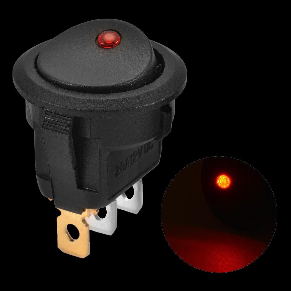
I prefer an immediate shut-off, the engine may crank and spark on start-up and then just crank without engine start-up perhaps once or twice. I also prefer a switch with an indication light, showing me the system has been switched on and this takes out the guess work of being on or off. (Fuel access - the light remains off if fuel shut off is active) some may choose one without a light indication and opt for a 2 pin none illuminating switch. The 3 pin will add a connection for the switch illumination and only illuminates during the driving session, preferably when the owner of the vehicle is driving hence the secrecy of the switch location and obvious knowledge to what this light signifies. To start the installation one needs to:
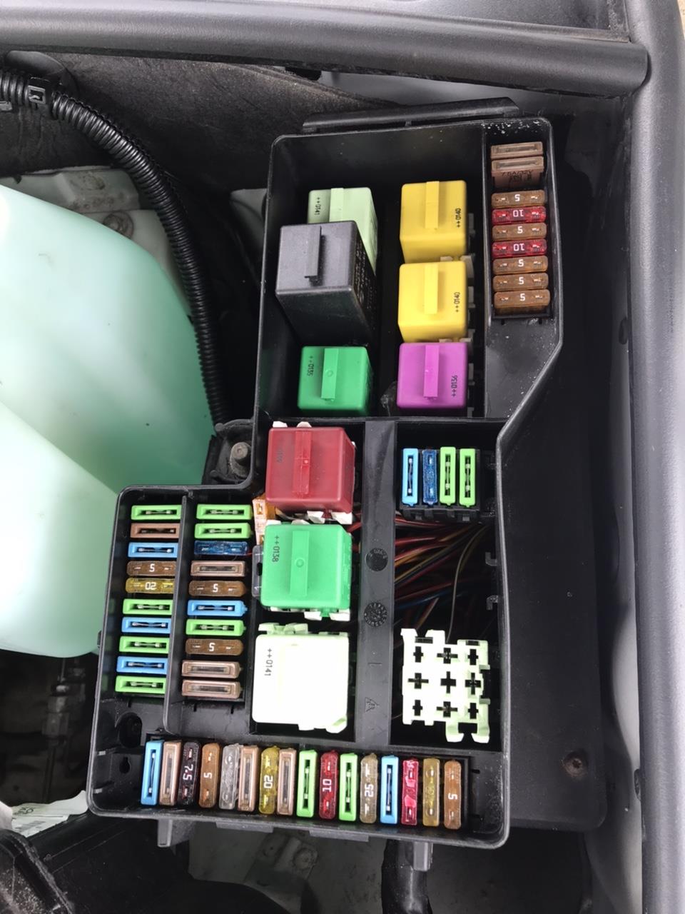
1. find a suitable position for the switch and mark the area, a drill will be needed to form the hole for the switch. 2. check the main vehicle fuse box for the fuse for the Fuel Pump and note it's position and fuse rating, (in my case the fuse rating read 15 Amps - Fuse coloured Blue). 3. Use 2 stranded wire to the length and distance from the fuse box, to the switch (from the fuse box under the bonnet/hood or inside the vehicle or underneath the dash area, under the rear seat whereby the fuse box may be situated. (check your Service Manual) One can also use the identified wires to the fuel pump in the wiring loom under the front dash if one is familiar with electrics).
Note: The access from under the bonnet/hood if relevant, through the vehicle firewall to the inside of the car is not always straight forward access. One needs to look for a rubber grommet on the firewall, to feed the wire(s) through safely, away from moving parts of the engine... Failing to find access or openings, a small hole may have to be drilled into the firewall to accommodate the wire(s). One will also need to purchase an appropriate sized grommet and to pierce a hole in the middle of the grommet to feed the wires through. The grommet is important and should prevent water from getting into the vehicle via the freshly drilled hole.
To tidy up the wires, it is advisable to place the wires into a length of black plastic corrugated piping; this is in-keeping with todays wire coverings and gives an added professional look. This tubing is cheap and can be obtained from most auto accessory outlets or via eBay. It also helps to camouflage any additional new wiring from potential thieves remembering 'time' is their key ememy.
DISCONNECT CAR BATTERY BEFORE WORKING ON ELECTRICS
Simple Diagram for Fuel Cut-Off Switch
Earth
Switch
New Inline Fuse
Fuse Box
Fuses
Fuses
Fuses
Relays
Relays
Fuses
-Wires attach underneath of the Main Fuse Box
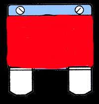
Typical Blade or Bayonet style of car fuse used in Auto Fuse Boxes.
Note: the centre of this fuse 'metal' should be cut out, (the 'S or Z shape') Keep the plastic casing in tact. The two pins on each side should not be damaged or making any contact with each other, the fuse now is deactivated or not being allowed to complete the circuit. This Fuse is to be replaced back into the main fuse box - Suggest one uses some coloured insulation tape as a reminder that the fuel pump fuse has been moved.
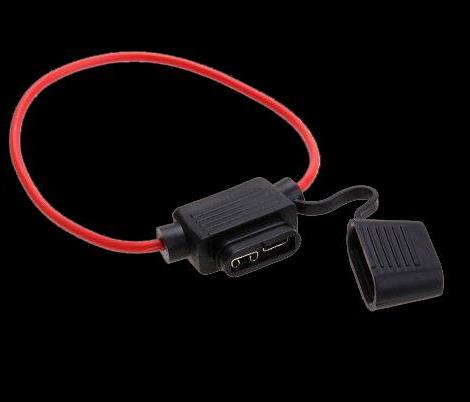
The inline fuse for your fuel pump has been replaced and is situated under your dash inside your vehicle.
- When the switch is turned off, before leaving the vehicle (light off) the car will NOT start and the engine may turn over, however will not run or will drive with very little distance, based on how much fuel remains in fuel feed pipe. - When the switch is turned on, (light on) the car will start and the engine will turn over and run. The only time the light should be illuminated is when the owner gets into the vehicle and turns the switch on to drive any distance. The switch should be turned off when leaving the vehicle. (Remembering to do this, can also be a problem and visa- versa....:)
SWITCH FUNCTION - (overview)
3 Pin
example:
- Re-insert a deactivated fuse into the fuse space for the fuel pump and as a personal reminder, place red insulation tape around the fuse as to blank out the visual aspect of the blown fuse. (This use of tape should not be noticeable looking down at the fuses).
Old Deactivated Fuse
WIRING THE SWITCH
FUSE
1. The darker pin on the switch is usually the earth. A wire can be connected using a spade connector on one end and a ring connector onto the other and then attached to e.g. a screw, making contact with the chassis. Make sure the earth is good, by rubbing away any layers of paint, substances or even rust as this will prevent a good earth or grounding. This wire only needs to be a short length to reach a suitable negative Ground point.
2. The remaining 2 silver coloured pins, again requires 2 spade crimp connectors to be connected to each of the pins coming from the fuel pump, in this case the two terminals in the fuse box will be used. Note: The switch light should be switched on, (light on)when entering the vehicle. This will allow the fuel pump to be activated, to feed the fuel to the engine, before ignition key is turned. If the switch light shows on for off and off for on, just swap the two spade connectors on the silver terminals to rectify this.
Tape Insulated Fuse is returned to Fuse Box under the bonnet (Z3)
Returned to Main Fusebox
Inline Fuse
X
BMW Z3 2.2i 2002 (e36/37)
Fuse Layout Diagram
Normally mounted under the dash inside of vehicle (Z3).
INLINE FUSE CONNECTOR
NOTE THE FOLLOWING:
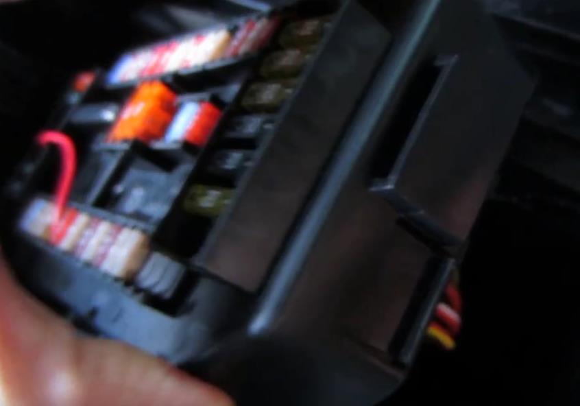
Typical location of Fusebox for the E36/37 Z3 Fusebox under the bonnet/hood 2002
Location and bolt/screws will vary on different vehicles and models
It is best to connect wires under the fuse box as to prevent the wires from being dismantled or pulled apart.
Try not to use fuse extensions on top of the main fuse box for this particular job, as these can be readjusted to reactivate the fuel pump and the car can be stolen.
4. Find the location of your fuse box, this is normally held together by four long, star headed screws, these need to be unscrewed and stored safely for the duration of this job.
Star headed Screws
BMW Z3 2.2i 2002
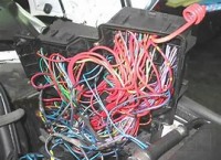
5. With the retainer screws out, prise the box up gently with a flat bladed screwdriver or hard plastic prise tool and try to position the fuse box as to see the bottom, a group or 'spaghetti' of wires and where the wire connectors insert into the bottom of the fuse housings.
6. By checking the fuse box lid pictured layout of the fuses and relays on your vehicle, look for the 'Fuel Pump' fuse. With the fuse tool extractor, or needle nose pliers, extract the appropriate fuse from the appropriate socket. (always double check you have the correct socket and fuse).
7. Search for the correct wires to the connectors, underneath the fuse box, this can be a trial and error and time consuming exercise, as the positioning of the box can be deemed as awkward, majority of the time, one is viewing side-on, as one holds onto the box, (one would need to disconnect all the connectors and relays to execute the job ideally, but this would be impractical and very time consuming; as reassembly could be a nightmare to the uninitiated), however by moving the wires or twitching them, the correct wires can eventually be identified. There should be 2 wires for the same connector socket (one for each end of the fuse, don't worry if they are the same colour as these are only going to be connected to two of the three terminals on the switch linked by your new extension wires). Make sure you have identified the correct wires for the correct fuse socket. It does not matter which two wires from the switch connect to the two wires under the Fuse box. Work can now commence.
Note: There are a number of ways of disabling this fuse socket, by removing the fuse, by cutting the wires and connecting to a switch, by splicing the fuel pump wires and dissolving part of the outer plastic skin of the wire; using a soldering iron and then soldering the wires leading from the switch to each of the identified wires. By adding an inline fuse incorporated along the circuit to the switch inside of the car in it's secret location, the fuse can be situated somewhere under the dash, leaving the fuse box fuse with the appearance of having a fuse, however the fuse will need to be deactivated, (no positive contact or to be seen as 'Blown'). The latter example allows for the original wiring to be maintained without too much damage (even if the new connections are hidden underneath the secured fuse box). The reason the fuse has been replaced by the deactivated fuse, is so it can be over-looked by the potential thief stealing the car. Remember 'time' is a disadvantage to an opportunist thief. Even though replacing the fuse will not re-activate the fuel pump, (as the new circuit and switch has broken the circuit, it is still time consuming for the potential thief and also hopefully; making them feel very uncomfortable.
8. At this point, and in this example, the identified wires under the fuse box, have had an isolated area of their outer coating melted off with the soldering iron and shows bear copper wire, the two wires from the switch has been attached around the wires and soldered for added security and can then be taped up with insulating tape. (note: if one has chosen to cut the two Fuse Box wires and solder onto the each of the switch circuit wires, shrink wrap can also be used to insulate the wires and seal the connections. (note: it can be a good idea to use the same coloured tape or shrink wrap as the wire within the fuse box where possible, the psychological aspect of this will help to add possible further doubt and confusion in the would be thief's mind, that's if they have managed to get to the wires under the fuse box by this time, this is most unlikely, but a well worth added measure).
An example of the type of 3 pin switch connector used.
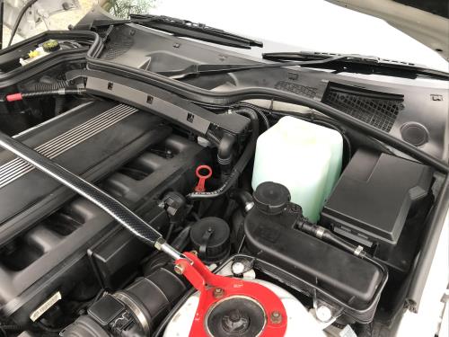
Engine compartment after the job was completed.
JOB DONE!
Powered by S-AM3l1A
<18>
Note: One recommends reading the diary first and then linking to workshop notes to maintain the continuity of the theme...
Don't let the 'spaghetti of wires put you off! Just find the fuse and follow the wires from that....
Update: 2022 - I later updated this switch to a two pin miniature switch (see 22 diary) - It can be hidden better without LED - Worked better without malfunctions...