It is highly recommended from various sources to fit this exhaust cut-off either below the downpipe at the front of the vehicle or just before the muffler at the rear of the vehicle. The rear usually fulfills legal or statutory requirements and is usually the most common position with this particular accessory.
It is all down to where to fit the new cut-off Exhaust? Space for a 'Y' pipe and fittings can be a challenge if using the sleeves and not welding. However there is some room for play and the 'Y' pipe can be cut at each end to reduce the 9 1/2 inches, taking off around about an inch. Note 1: with the sleeves overlap on each end, extends the 'Y' pipe length to at least 10 1/2 inches before cutting. Do Note 2: As with my exhaust, the slide on, tail trim's diameters on the end of the exhausts appeared to be 63mm; making the exhaust around the 60- 60.5 mm in diameter. (Note: do not use this as the only reference of the diameter and circumference size. Check along the full length of the exhaust as the circumference may vary in some sections of the length). My 'Y' pipe is 63mm, (over sized for the exhaust in question) in diameter and this should allow the existing attached exhaust pipe to slide into it, this can help in providing more available pipe for the brackets or clasps to be attached. With the attached regular exhaust pipe being enclosed into the Y' fitting, this should help seal the exhaust in theory. The 63mm clasps or sleeve brackets can slide onto the 'Y' pipe further, as it can clamp onto the outer as well as the inserted attached pipe based on the correct inside diameter and length. In addition, the 'Y' pipe can always be cut at each end if required, if there is not enough length to the existing exhaust; as previously mentioned, allowing further space for both the pipe and both bracket's length overlap. A case of trial and error in this case, as the Z3 has had extensive changes and variations to models of exhaust systems, stock and after-market systems.
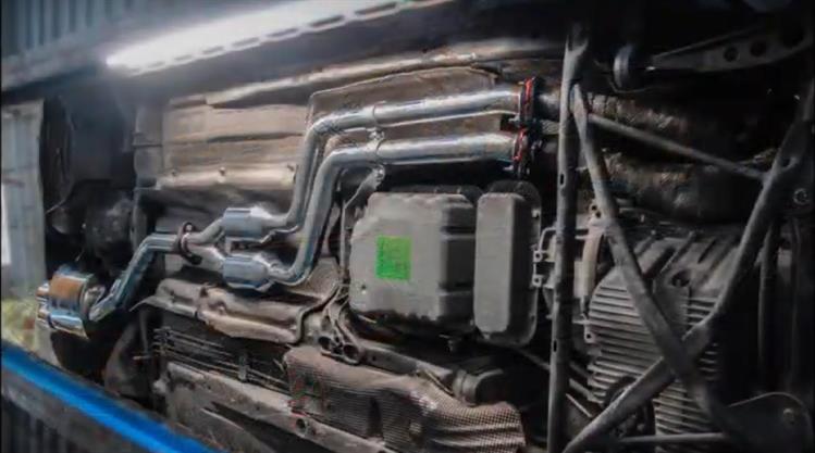
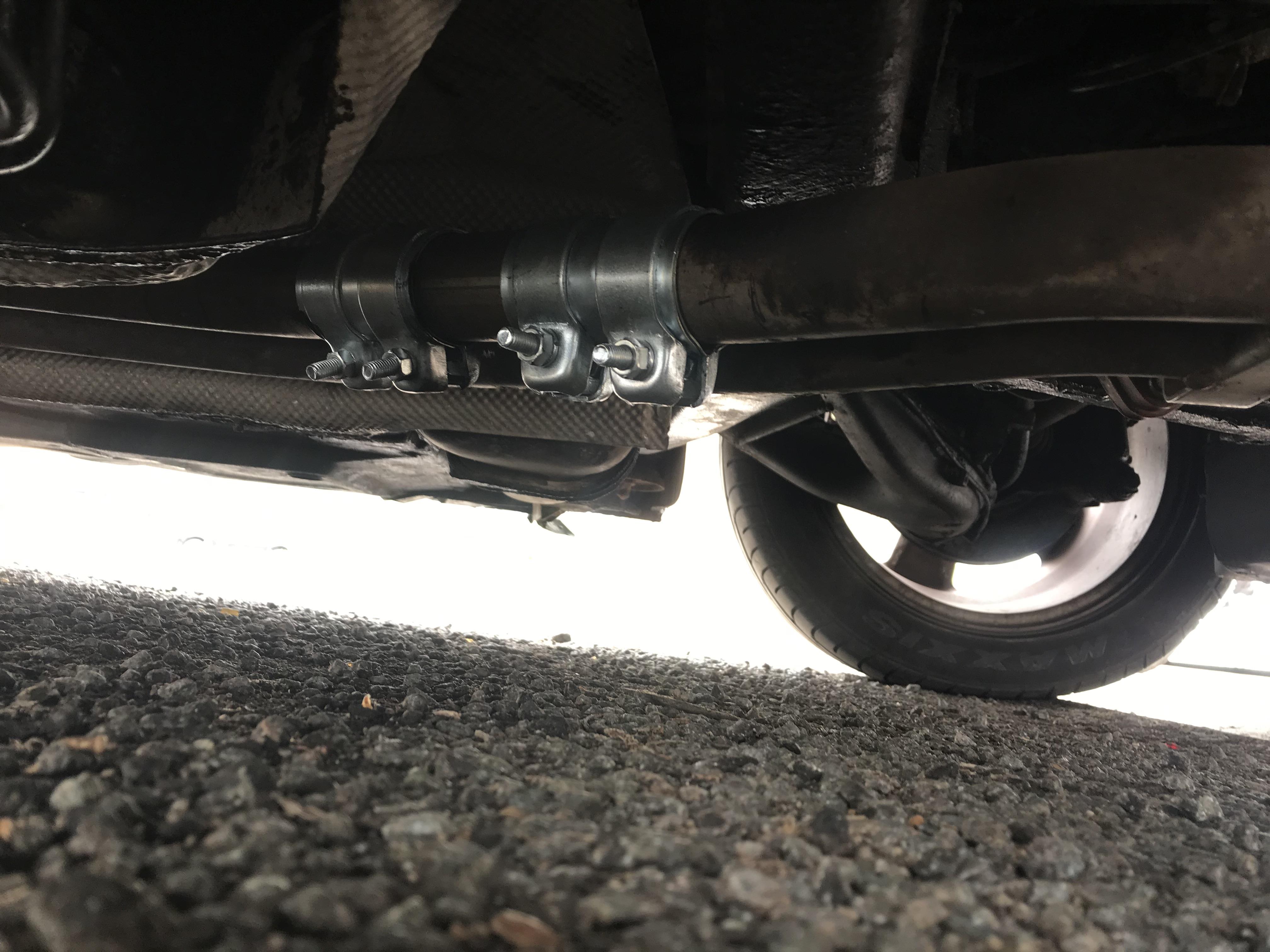
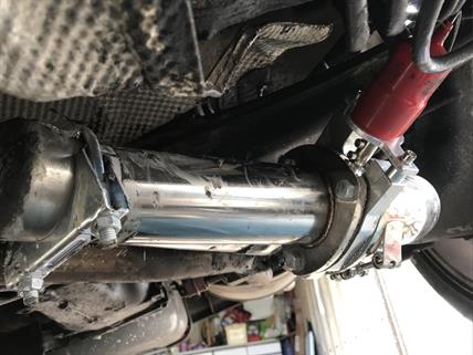
Four possible areas on a fitted exhaust system as indicated on the image above and the spaces available?: 1. Is the most common position towards the back muffler and recommended. In this image, there is only one pipe at the rear muffler end, however the position is viable for the twin exhaust, one must point out the length is tight, (only if one avoids cutting the chrome 'Y' cut-off section pipe)... 2. Is a second alternative before the cats, also note the exhaust hangers or supports, (Note 3: accounting for different z3 models and exhaust variations) 3. Is a possibility, however space for the cut-off motor could be a problem, this is doable if the depth and space are available to house the cut-off motor...? 4. Note: 4 2 to 4 there could be a problem legally as this may cause problems with emissions or when it comes to testing based on country and geographical regulations. It is ok if just using it for track only.
Note 5: If fabricating is to be used; (using a welder of any kind); this will open up more options to the positioning of your 'Y' cut-off unit without too many restrictions when it comes to positioning. Research the variations in design and sizes of the exhaust 'Y' cut-off before purchasing, as some have been designed specifically for fabrication and this will help in the fitting and sealing of the unit.
Note 6: Different techniques of fabrication are used when using Stainless Steel and is most compatible with the full Stainless Steel Exhaust Systems, rather than mixing the metals of standard stock steel exhaust systems, with the stainless steel. Before tackling this scenario one should be a competent welder or at least seek professional advice, or even list the services of a professional welder to take on this task.
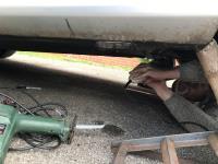
My second attempt of fitting the 'Y' cut-off without fabrication, was on the 12.04.19 - a combination of tools were used: Grinder with diamond disc, reciprocating saws. This exhaust system was a through twin pipe, after the CATS, cutting a section length of around four inches (102mm), the thickness of the rim was at least a good 2-3mm and could be described as thick gauge and was definitely manufactured to last. The o/s pipe of the twin exhausts was chosen and cut; mainly down to locating a position for the motor attachment and to prevent contact with raised manhole covers or speed bumps on the road. (update: space is tight and may still make some contact with the road initially, however check your bracket clearances and turn them away from the ground, preferably in a horizontal position to the road, allowing for access to the bolts on the brackets - (this seemed to do the trick, keeping it clear of the road surface).
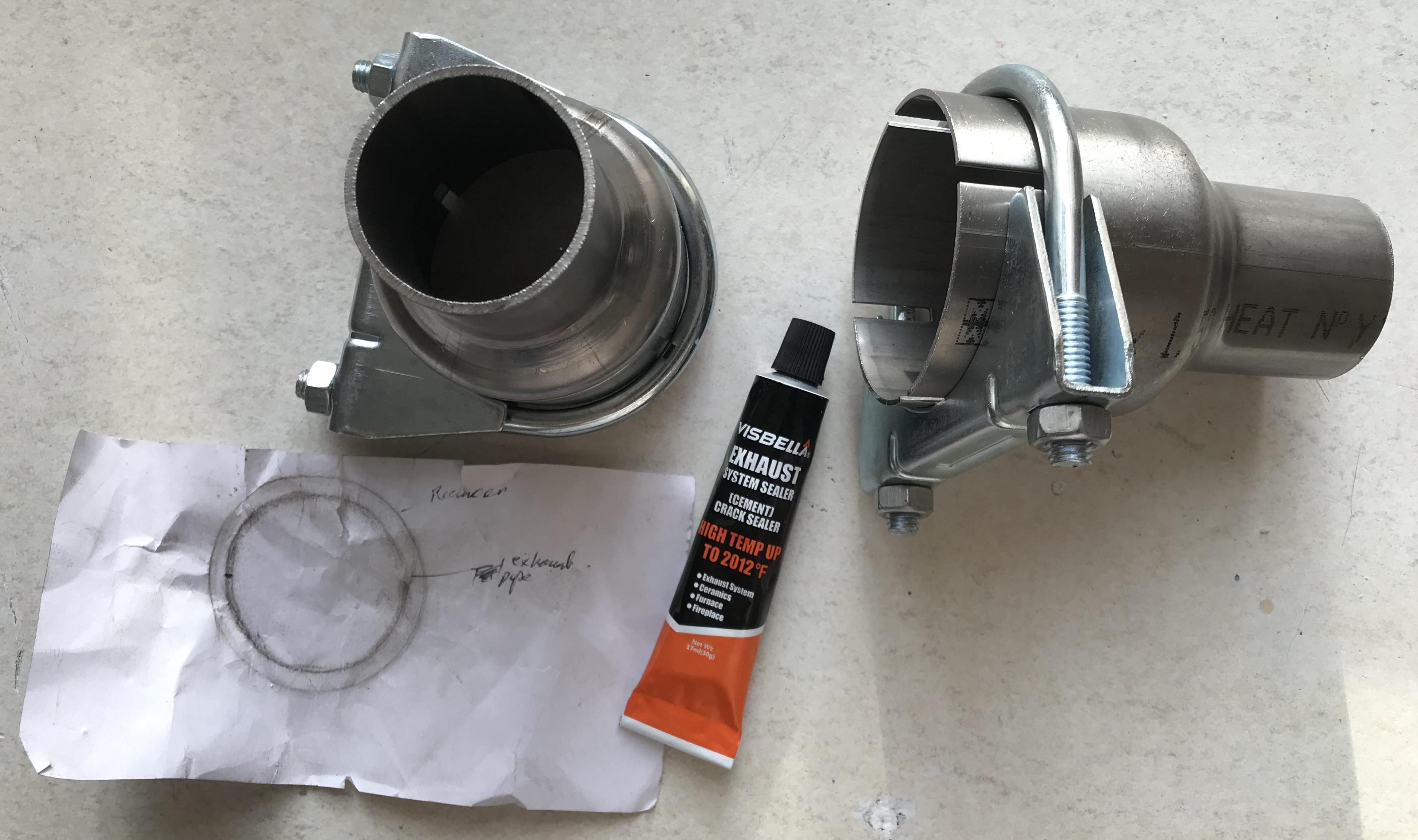
Unfortunately, when I came to measuring my exhaust circumference and diameter, it was miles out and it was fortunate that only a small section of the o/s pipe had been cut. When measurements were compared to the diameter of the 'Y' section of the cut-off, it could have been compared to a blackhole, (Even though measurements and assumptions were made at the time and thought correct, to use an analogy, when comparing the cut off section and placing it inside the 'Y' Cut-off unit it was like a straw in a teacup the exhaust pipe was much smaller in diameter and somewhere along the line we had made a 'big' blunder). With hindsight, measurements should have been taken along the full length of the exhaust, instead of treating the full length as the standard size, it was a big mistake. We now needed to remedy the miscalculation, a couple of reducers would be required for both ends to fit the 'Y' section and the 37mm exhaust. A large decrease in size. For today at least, this only left one option and that was to carry out a makeshift repair, until we could source the correct reducers and parts. We also needed initially, two sleeves, (49.5mm) for the repair and these, were to hold and envelope the 37mm diameter exhaust on the vehicle. To make the problem more problematic, the sleeves were situated at two different retail outlets and were miles apart in a rural area, this was to be time consuming, this meant racing across the country to pick them up. The old section of pipe was eventually re-attached after a cleanup of the surfaces and the sleeves were then positioned and bolted up, straggling the joints. On starting up of the engine, there was a little blowing from the sleeve joints, (this also required exhaust putty to make a full seal, however non was available at this time), the noise level was a little loud but adequate to get me and the vehicle back home, 60-70 miles away without being pulled over.
1
2
3
4
1997 2.8 E36 Roadster
The job of Installation, procedures and images are Pending better temperature or weather conditions..... we are talking about the UK! Currently rainy season..... April, May and June 2019
Until we order and receive the correct reducers, this job will be placed on hold for the time being... Until the next time the job is attempted. Watch this space! (See diary 12.04.19 and 14.05.19 for more...)
Stock picture
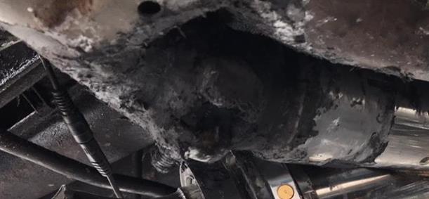
Cutting the exhaust pipe
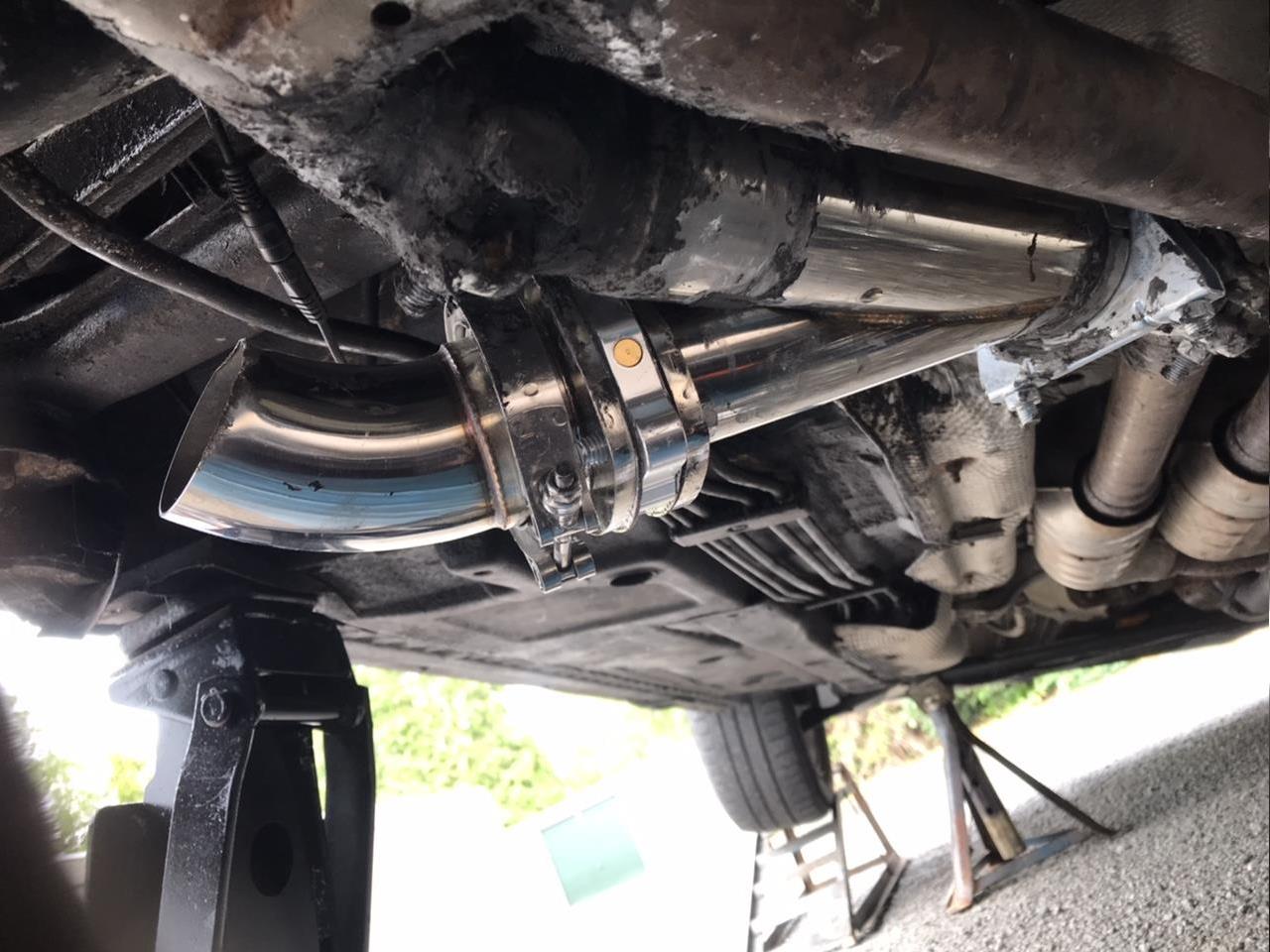
Repaired exhaust pipe
26.04.19 BMW Z3 2.2i 2002
Remember this?
All sizes of reducer, metal bending to personal specifications. This was altered to the 'correct' dimensions and another one was also purchased with 2x conventional exhaust clamps and putty.(See next page 17c and diary for details).
When it came to fitting the reducers, they just didn't fit into the aperture of the exhaust, even when grinding them down, we concluded the thickness or outer diameter was accounted for, however the inner diameter thickness width was not. We were told it would be a tight fit, this was an understatement at it's best.
The following items were purchased to remedy the problem:
17 xiaolan72 £5.68
zakautoparts £4.39
keepsgood £4.52
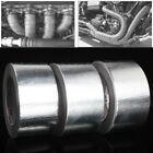
The silver tape is designed for exhausts and used effectively on downpipes. It is strong and does need scissors or a Stanley styled blade to cut it.
Even though the putty came in a 250g tub it proved to be enough for this particular job. This was a new product on the market and proved very effective.
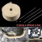
The Bandage Ribbon is just over 1cm wide and has a thick weave, it is also very effective. Also supplied with steel zip ties, (being metal, the zip was difficult to tighten up).
There were a number of choices of how to proceed with this job and the following sequence was chosen:
1. (In my case) Clean the areas with a wire brush to get the old remnants of putty off, scuff up the metal, this will also allow the tape to adhere to the surfaces.
2. Wrap the silver tape around the exhaust, starting from any available length of exhaust within the work area, over the small end of the reducer length with overlaps, especially over the join areas and emphasising plenty of overlaps at each end. The brackets will need to be manipulated over the tape and ribbon, avoiding tearing, (this can be awkward and time consuming if using sleeve type clamps). I would suggest at least three layers of tape over all, and a couple more over the join areas. Note: the clasp or bracket may need to be widened to allow the thickness of the tape and ribbon - (the wider the bracket, the more awkward it can be in pulling the clasp back together with the sleeve type brackets reinstallation, (The one's I had were off a sleeve and with hindsight, I would have used a conventional clasp, with the correct circumference of the exhaust pipe if these had not already been purchased for the earlier repair job).
3. Feel any dips in the exhaust tape, especially over any covered hole(s), (as in my case) these need to be filled with exhaust putty, this will probably not need much.
4. The 1 - 2 cm ribbon bandage length should be measured and cut, (Z3) 30 and 60 cm lengths and then tightly wrapped around the pipe on top of the exhaust tape, (not forgetting the overlaps) the ribbon came with metal zip styled ties and a couple were used to retain it around the Y' Pipe. The clamps will also help in retaining the ribbon bandage, (that is if it chooses to 'play nicely for you', as this is not always the case as the metal clips can slide).
5. The final process is to coat over the tape and the ribbon bandage with the remaining putty; this includes spreading over the ribbon, in and around the clamps and joins letting the one side of the cut-off 'y' section to dry naturally, whilst commencing with the other more difficult side, in this case the one with the angle and chasm due to the miscut on the angle...
The directional chrome nozzle on the end of the cut-off clasp proved to be a little low and needed to be manipulated; as to avoid road bumps or obstacles.
After the fitting and the repair, it did look a little unsightly, mainly down to the exhaust putty, one has the opportunity to use a wire brush and a high temperature paint to rectify this if one wishes. I chose to paint the two sections of the twin pipes both localised within the work area; also before and aft of the work area as well as some of the chrome 'Y' Section, leaving the motor unit and the chrome nozzle and as one can see, it does make a difference. (see last two images below).
Black Painted Section - looks better in appearance
Motor and Nozzle Left Unpainted (through personal choice)
Note: The Slight angle from the reducer to front of the pipe
The same sequence was adopted, on the 'bad' side of the cut-off, with emphasis was on the large chasm, down to the angled cut, this needed an adequate amount of silver tape wrapped around it, that is to say; a number of layers and then a good 'dollop' of putty spread to fill-in any indentations, (don't be shy in getting your hands dirty and around the pipe, especially if the pipe is still attached to the vehicle, all possible gaps will need to be filled before wrapping the ribbon bandage around the pipe, overlapping as one goes and then repeating another layer of exhaust putty.
There were problems with the 'marrying up' of the sleeve clasp, (note the clasps used, were off an exhaust pipe sleeve previously used on the first repair job, however a standard and correct sized conventional clasp should most likely do the trick and may be more easily accessible when screwing back on the nuts. The only reason the one sleeve clasp was used in this task, was they had already been purchased and money was tight, they were used to save on costs, or so one thought..... However, the follow-up repair was now complete.
The time had now arrived to start the Z3 and allow the engine to tick over for a couple of minutes; this allowed the putty to go off and become much harder, due to the heat of the exhaust. (Note: don't rev the engine, if there are leaks from any of the joins or via the edges of the sleeves, (there shouldn't be, if followed the above procedure correctly) it will displace the putty and this will jet off to the next county, leaving one in the 'dragster zone and one will' be having to replace the putty for a second time. Do also note, without the use of tape, condensation from the exhaust will prevent the putty hardening, so the tape is a useful commodity. A good opportunity to also tighten bolts.
With checks all around, crawling back under the car and checking the pipes and joins, the job seemed to be successful, after observing and feeling around for leaks; I did notice this was not at all a pretty job and decided to blacken most of the chrome and a couple of sections of the exhaust pipe generally, just leaving the motor unit and the chrome tail spout of the cut-off. On completion, the job looked a little better in appearance for me at least.
With remote in hand, the time had come to test the cut-off in action. There were definitely two distinctive sounds or tones from the exhaust. After repeating the action on the remote a few more times, I concluded it was a job done, now at least I can put this part of the job to bed - Job Done! (or so I had thought, see diary entry dated 05.06.19).
Update Note: Eventually, this job was completed successfully without welding, after further adjustments and the rotation of the chrome tailpiece clasp. One just needed a little time to assess the durability and the duration of this latest repair, a number of weeks on, so far it has been performing well.
The good thing about an electronic cut-off, one can instantly rectify the problem of emissions and noise. One has the choice with the latter especially, whether to be a pain to the troublesome neighbour(s) or not, just by opening or closing the valve.....sweet!
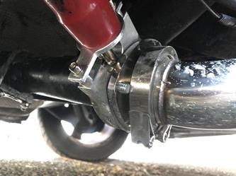
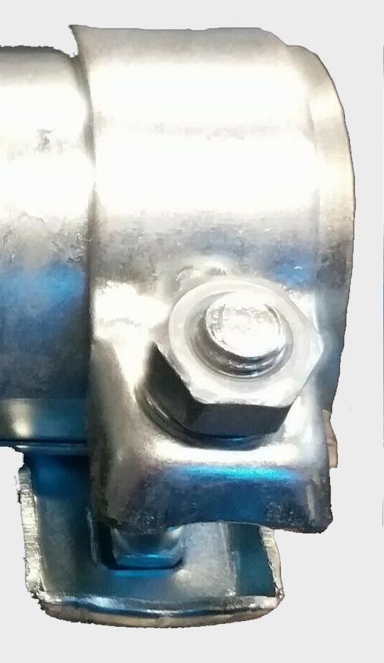
Sleeve Exhaust Clamp try to avoid this style
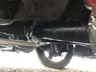
Note: The back box pipe here is just one pipe, not two as with some model Z3s - the one pipe version in this image makes the fitting much easier. With this particular example at approx. 62.5mm diameter is ideal for the 63mm Y' cut-off. (Check exhaust sizes before purchasing the 'Y' cut-off that will complement your exhaust system on your vehicle). It was unfortunate for me in some ways, to have had the twin pipes with the varied length diameters. The only place one could insert the Y' cut-off was in the n/s section of one of the twin pipes measuring only 37mm diameters, this also requiring two reducers.
This was the more difficult side as one can see....
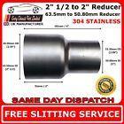
Reducer
Sleeve Clamp
Wrap the silver tape and Ribbon around the pipe... Manipulating the bracket over both wraps and finally, position the clamp over the join. Fill in-between the bolt using putty and smooth evenly.
Rear
Front of vehicle
'Y' Cut-off
y Cut-off section - after the black paintover
y Cut-off section
IMPORTANT:Try and get the correct diameter and circumference of your 'Y'Cut-off for your size of exhaust before ordering - this will save on time, money, work and patience...
Note: Some exhausts are custom and can vary in diameter and circumference along it's length. Be aware of this, especially when positioning the unit.
Filler
Note: One may need to turn the clamp bolts collars away from the road this will help in preventing contact with the road
Cut Out Slot: 18mm wide X 37mm
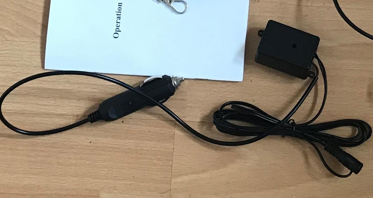
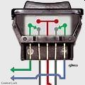
Electrical Connections 1ST TERMINAL ---- MOTOR = positive or negative pin from cut-off motor 2ND TERMINAL ---- NEGATIVE (earth) 3RD TERMINAL ---- POSITIVE(MIDDLE) Cig Lighter pos+ or battery 4TH TERMINAL ---- NEGATIVE (earth) 5TH TERMINAL ----MOTOR = negative or positive pin from cut-off motor
Both earth wires, (black) can be twisted together and then grounded onto an earth point on the car chassis or onto the negative - post on the battery)
Note: Don't use the remote 'brainsbox or lighter adapter' that comes with the exhaust cut-off, the wire that has the male or female connector from the 'remote brainbox can be cut and the two wires can be connected directly to the switch pin 1 and 5. (doesn't matter which of the two wires goes to pin 1 or 5). Don't forget to have an inline fuse on terminal 3 - middle pin that connects to the LIVE supply, (battery + OR + pin on cigarette lighter or additional cabin fuse box - 20 amp initially to 25 amp fuse, maximum - (start with the lowest fuse rating first).
x
x
cut
Rather than use the lighter insert connector, you could just cut that off and connect inline to the ignition live supply via a switch, the other wire and switch connector to a good earth point. (discard black box and lighter adapter). Be aware of any resistors that may have been included within the lighter adapter if applicable.
I chose the 5 switch connector, this worked well enough without any additional add-ons.
Do Not use the Remote or 'Brain' of the remote unit if one elects to use a separate switch. The switch will not function. However, include an inline fuse in the wire-up (live).
See Diary 2019 entries for further references: 12.04.19, 25.04.19, 11.05.19, 13.05.19, 14.05.19, 19.05.19, 20.05.19, 31.05.19, 05.06.19, 18.06.19, 22.06.19, 25.06.19, 26.06.19
Not the ideal clasp, however can be used
Before treated with a black paintover
The Spout was left unpainted
My 'Y' Cut-Off had been ordered prior, basing the exhaust system as being standard or stock, with a 62.5mm diameter on the backbox and taking this measurement from the tailpipe trims of 63mm section, perhaps I had been a little naïve at the time...
LESSON:
Note: the rim measure the outer rim and the inner rim of the exhaust for compatibility as to fit.
One may want to rotate the clamps to prevent bolts making contact with the road if refitted will try to angle it higher, this may require a welded metal insert .
Wiring up the 5 Pin Switch to the Exhaust Cut off- The second part of the job!
One has a choice either to use a remote styled keyphob that comes with the kit or a 5 pin switch, one will need to purchase separately. They both have their advantages and disadvantage. Using the remote over a period of a week did prove cumbersome on the bunch of keys to the ignition. I elected to install a five pin rocker switch on the car dash and this proved more favourable to me.
Conventional Exhaust Clamp Probably the better choice of clamp
Powered by S-AM3l1A
<17b>
Note: One recommends reading the diary first and then linking to workshop notes to maintain the continuity of the theme...
A welder would be good at this point if one has one!
update: 2022 Perhaps not the prettiest of things, but it works well! The tape ribbon helps with the cosmetics and it does get through the MOT without any hassle..so far. If doing it again, would weld it, YES! I didn't have a welder at that time.
Works well - Job Done!
*You may want to add a fused relay and this is probably a good idea. (updated 11.05.24)