This must be about the most ambitious engineering project a single person conducts privately. To be honest, I feel very humble besides this effort of Andreas Petzoldt who did most of the calculation, construction and design work of the device described in the following, on his own. It took him about ten years and lots of funds to get so far. I’m very grateful that Andreas permitted me to share the pictures that I took during a visit to him, with all people interested in this kind of stuff. Eventually this part of my page will be moved to Andreas’ own page once he has set-up one.
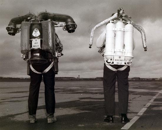
Now, what’s this all about? Andreas is designing and building a turbine-powered personal flying suit. In principle this is going to be similar to the well-known “Bell Rocket Belt”, the difference is the power plant and controlling of the unit. While the “Rocket Belt”, originating form the late fifties /early sixties, used two monopropellant liquid fuelled rocket engines
(peroxide motors), Andreas decided to go for a gas turbine, driving a huge fan to achieve a high mass flow of air. This air will be directed to four variable thrust nozzles that will produce the thrust necessary to lift and control the device. The endurance of this flying machine would be much longer than the approximately 30 seconds possible with the “Rocket Belt”. Preliminary calculations suggested a figure of about 20 minutes or so for one tank full of fuel. Andreas decided to build everything himself, even the gas generator engine since at the time he started work on this unit, small commercially built gas turbine engines weren’t available to the public as surplus easily. So he chose to use a rotor of a large KKK brand turbocharger. And now for some pictures:
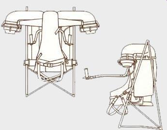
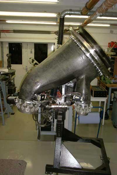
Here’s a view of the complete device so far, less the turbine engine that is still on the test bed. More information on the engine follows later. The pilot fastens himself between the big front lift nozzles with leg belts and a cross-belt at the chest. He has got arm rests with the control “joysticks” to maneuver the unit. The current control stick will be replaced by professional ones later. Of course there would need to be another control panel added to operate the engine and view the condition of the unit (N1 and N2 RPM, EGT, oil pressure, oil temperature, fuel capacity, possibly fan pressure ratio...). The whole cold air ducting is made from carbon fibre laminate. All mounting points and flanges are entrapped within this laminate to allow maximum strength. The fan of 60cm diameter is located behind the pilot’s head, tilted 45° backwards.
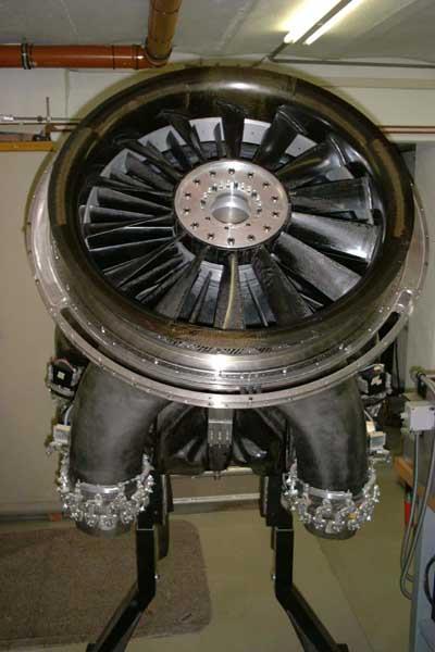
Here’s a front view of the unit. The large metal ring around the fan air casing shrouds the fan perimeter turbine. The whole device, once assembled completely, will be relatively heavy, about 120kg. This requires the use of some kind of light-weight stand, possibly with wheels at the base to allow the pilot to move it while earthbound. The current stand is used only for assembly.
<<< This side view shows the arrangement of front and back nozzles. The wiring between these nozzles is for ground testing of the control mechanism only. At the fan section, the large, rotating inlet lip is visible. this part is also made from carbon fibre material.
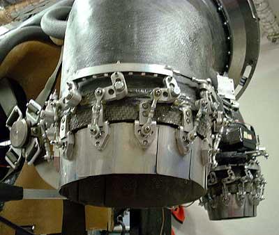
The fan is made from separate laminated carbon fibre blades. These blades consist of a core that is made of carbon fibre rovings, tensioned in axial direction and guided around a metal bushing at the mounting eye. This way the fan blades will stand the axial load without any problems. The surface of the blades is covered with woven carbon fibre material to provide the necessary rigidity in the lateral direction. The mold had been manufactured from solid steel blocks with CNC wire EDM (electric discharge machining). At the outer perimeter of the fan ring (made from heat-resistant titanium alloy), a turbine is located. Three blades are visible inside the part-span circular slot at the lower area of the turbine shroud ring. This turbine is only partially charged with hot-gas (about 1/3 of the circumference), the remaining 2/3 the blades run in the shrouded upper area. The gas generator will be mounted between the rear nozzles and tilted at an angle of about 45° upwards. The hot gas stream will be ducted by an Inconel formed sheet metal volute to the power turbine section. Andreas is currently designing this volute and making the sheet metal working forms. After the hot gas passed the power turbine, it will be guided rearward by an adjustable diffuser. This diffuser will allow to gradually deflect the gas stream left or right to provide a control function just like a helicopter’s tail rotor. These parts still also need to be made.
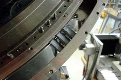
Here’s a close-up of the fan perimeter turbine. Three of the turbine blades are preliminarily attached to the titanium ring. Especially made threaded Inconel bolts are used for this purpose. >>
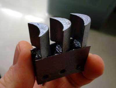
Here’s one of the turbine blade segments. These are made from carbon composite material. A core structure of carbon fibres with ceramics lattice to provide rigidity, is covered with a layer of ceramics to prevent the carbon material from oxidising. This material equals the heat deflection shield material of the space shuttle. Yet Andreas isn’t happy with some of the material’s properties, i.e. its relatively brittle, rough surface. So he’s considering to form new blades from Inconel or nimonic sheet material which would be way less prone to fracture. >>
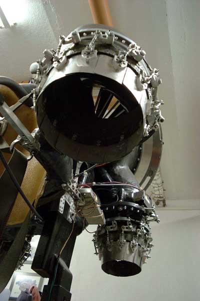
That’s one of the front nozzles with the actuating mechanism. An unison ring moves all the levers that actuate the flaps of the thrust nozzles. Though this system works very well already, there’s still a little room for improvement. >>
The second picture is a view into one of the front nozzles from below. You can see straight through to the fan. The fan discharges its air into a sectioned plenum area with a segment for every thrust nozzle. This way the nozzles won’t affect each other’s air supply as much as if they were fed from a common plenum. Whether the fan will be able to handle the varying flow characteristics still needs to be determined experimentally. >>
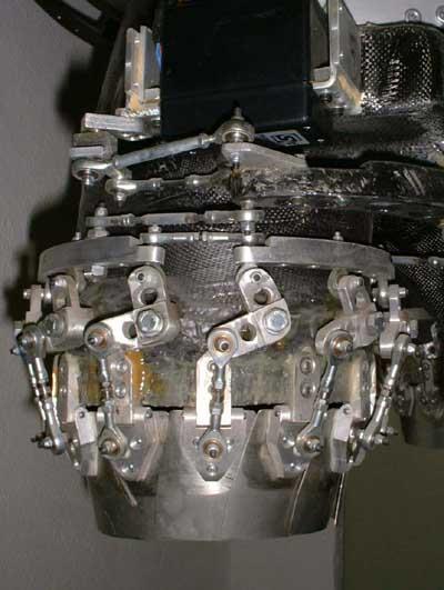
<< Here’s a close-up of the rear nozzle actuating mechanism. This is really great engineering work. The only one thing I don’t like too much is the actuator itself. It is a single high- power servo for R/C models. Though these devices might be pretty reliable, I think they simply aren’t the right choice for this application. At least if there is no redundancy in this critical application. This is a “monster” servo of high quality, but today there are similarly powerful servos available in smaller size so more than one of them could be arranged to form a redundant array. Also the current electronic control and mixing system needs to be replaced by something more sophisticated and reliable. This will be one of my contributions to this project. It will also need to provide an interface for a gyro to stabilise the unit.
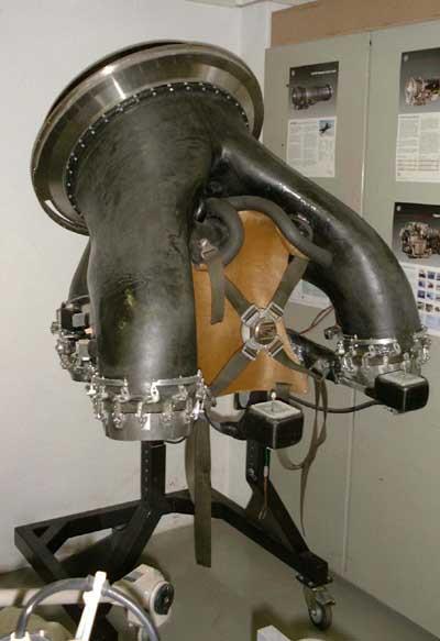
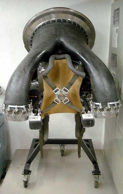
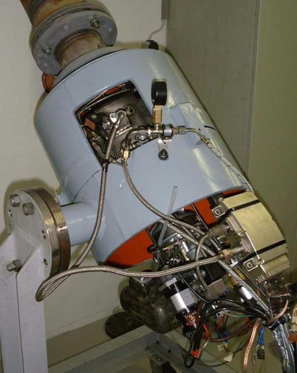
This is the complete engine on the test stand. It is already oriented the way it will >> be mounted in the “flying suit”. The large, grey tube segments are a multi-layer steel shroud to form a containment, just in case. Andreas is aware that this shroud won’t
contain the debris of a catastrophic shaft failure but it might serve its purpose if the compressor wheel fails. The window in the upper half of the shroud allows access to the main and starting fuel connections as well as the ignition system. Andreas uses a rotor of a large turbocharger which he modified to permit an overhung (cantilevered) bearing arrangement. This way all the bearings and mechanically sensitive components are located in the lower, cool area of the engine, projecting from the shroud. The complete engine (less the shroud of course) weighs just about 30kg.
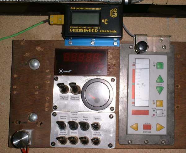
And that’s the engine’s control panel. There are lots of switches that control all the functions separately. No sequencer so far. And that would be my second contribution to this project, a governor/sequencer to be able to control the engine more easily. Not that Andreas has any problems starting and operating the engine manually, but when it serves its duty in the “Flying Suit”, the operator will need to put his attention somewhere else than at the engine control panel before he starts his engine he has to manually engage the starter clutch since the electro magnet provided for this job, is a little too weak...room for future improvements ;-). Then he energises the starter at low power to wind up the engine to about 3000-5000rpm. At this speed (after 18s of the video clip) Andreas energises the ignition system and the starting burner fuel valve which results in an immediate increase in engine speed. When EGT reaches 300°C (at 26s) he operates the proportional valve to meter fuel to the main burners. When passing 12krpm the starter is deenergised and the starter clutch retracted. At about 40krpm (45s) he deenergises the starting burner fuel valve, noticable in a short decrease in rotor speed. Unfortunately the microphone of my camcorder has got a little problem with the extreme noise level the engine produces in the confined space of Andreas’ workshop, but I think it’s impressive nevertheless.
As everybody can guess, this fascinating project has already consumed lots of money, not to speak of the thousands of hours Andreas spent calculating, designing, arranging, assembling, testing... Since he got no third-party financial support during this project, he had to pay everything himself. Only few components had been provided by turbocharger- or turbine engine manufacturers for free. So he is currently looking for some sponsorship to continue his project. It will probably still take some years until the unit will be ready for the first flight tests and unfortunately it doesn’t offer much surface for company logos or the like, but I’m pretty sure anywhere it shows up, it will attract a lot of attention.
25-Jetpack-Andreas’ Personal Flying Suit (“Monocopter”) Project