BMW Z3
Workshop
CLASSIC BMW (RHD-UK)
Repairing Factory - OBDII Wiring
Useful Information
To Engine Compartment
Firewall Gromet
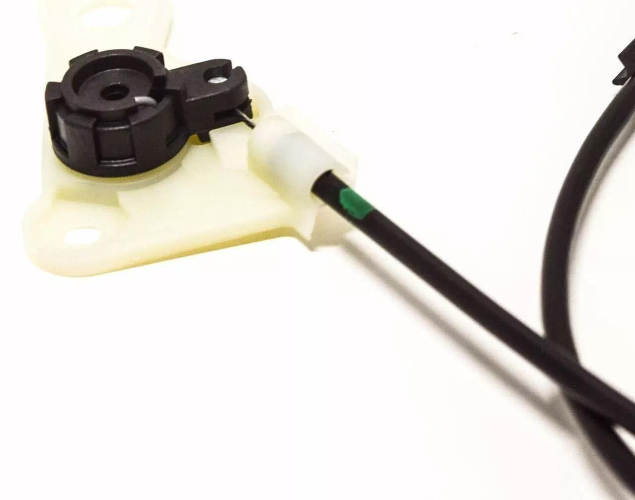
Lever Mechanism- Interior
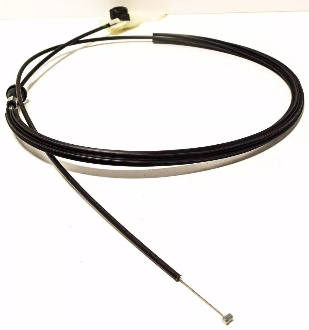
Z3 Bonnet Cable
1
LHD
LHD
Wire Colouring
No Liability - Use a test bed first, to test electrical circuits
Note: One recommends reading the diary first and then linking to workshop notes to maintain the continuity of the theme...
© Copyright Reserved - United Kingdom
Ideal Screen Composition 1680x1050
Main Menu
Chapters
Workshop
Tools
Publications
Diary
<34>
amplified
connection
Aerial lead
connection
Actual
Actual
Actual
Actual
Actual
15.09.24 - The rain had stayed off and it was a walk up to the garage to reinstall the aerial, déjà vu. The external aerial fitting proved a bit of a hit or miss, as the Chinese or imported rubber grommet that originally came with the electrical areial was not going to work for the original factory aerial, this was expected. The aperture was too wide, (remembering, that the pack of grommets came with a number of different, styles, types and designs of grommets, for the electrical aerial however; these were only suitable for the electrical aerial).
I decided to use a customised approach by deleting the rubber grommet and using a plastic purpose surround instead, (this also came in the bag of grommets). I was not sure how I would fit or anchor this plastic surround down to the bodywork, reluctantly; I decided to use some strong glue, sticking the plastic surround to the bodywork or the rear wing, the aerial poked through the wing and the aerial stalk was screwed to the main inside fitting, the aerial stalk now also poked through the plastic surround, (also making sure there was the thread making contact with the exposed wire and I added a few of appropriate sized rubber ring seals over the aerial stalk, two were inside the boot and there was one on the outside, so three in all. This slightly overlapped the plastic aperture giving a small lip all around. Hopefully, this will keep the water out. The aerial seemed firm and was as secure as it was going to be. The appropriate wiring was connected from inside of the boot/trunk and this just left me with the testing of the radio. The radio tuned in ok, it seemed better than I expected and better than the previous attempts of trying to install the purchased newer aerials that failed dismally. The initial tuning was done partially within the garage and was a good gauge for the potential reception, this was even better outside the garage and with the soft-top up so; it looked like this job was done, not before time.....another way to look at this repair; it had saved me over £100+ by repairing the original factory aerial and with held breath, for a change, it worked! It seems one can lose most of the time but on an odd occasion, have a win as it seemed in this case. Great!
Critical Wiring Notes for Z3 Owners
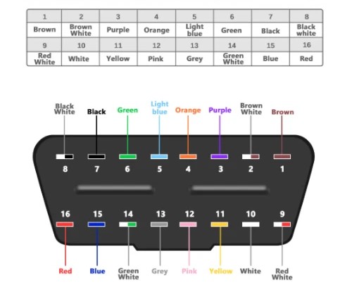
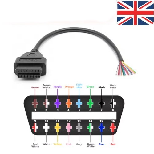
The "Shorting" Mod: On many Z3s (and E39s before 10/2000), the interior 16-pin OBD2 port only accesses the Engine (DME) and Transmission (EGS) because it is wired only to Pin 17. To access all modules (ABS, Airbags, Instrument Cluster) via the interior port, you must electrically connect Pin 17 and Pin 20 (and often Pin 2) together.
Many aftermarket 20-to-16 pin adapter cables have this short built-in.
Alternatively, some users solder a small wire between Pins 17 and 20 inside the 20-pin protective cap.
Pin 15 (L-Line): Essential for older BMWs (pre-2000) using ADS (Assembly Diagnostic Software) mode. If your scanner cannot communicate, ensure Pin 15 is populated and has voltage.
Protocol: The port primarily runs DS2 over K-Line at 9600 baud, 8N1. It is not standard OBD2, which is why a specific adapter or interface (like a K+DCAN cable with an ADS switch) is required for full functionality.
For most diagnostic tasks on a Z3, Pins 14, 15, 17, 19, and 20 are the most critical connections to verify.
For BMWs made after 2000 (specifically from July 2000/2001 onwards), the diagnostic protocol shifted from the proprietary DS2/K-Line (used in the 20-pin port) to the standard OBD2 16-pin interface using K-Line and eventually CAN Bus (D-CAN).
However, if you are accessing a 20-pin port on a transitional model (like a late Z3, E38, or E39 produced between 2000–2001), the pinout remains largely the same as the pre-2000 standard, but with a critical distinction regarding Pin 15 and the CAN bus.
Key Differences for Post-2000 Models
Protocol Shift:
Pre-2001: Relies on K-Line (ISO 9141-2) via Pins 17 and 20. Requires ADS mode (Pin 15 active) for full module access.
Post-2001 (16-pin): Transitioned to K-Line (1998–2007) and then D-CAN (March 2007+). The 20-pin port was generally eliminated in favor of the interior 16-pin OBD2 port, except for the Z3 and E38 7-Series which kept the 20-pin under the hood until the end of their production.
Pin 15 (L-Line) Status:
In many post-2000 models with a 16-pin port, Pin 15 is often not connected or unused for standard diagnostics, as the car wakes up via CAN.
In the remaining 20-pin ports (e.g., late Z3), Pin 15 is still critical. If Pin 15 has voltage, you must use an interface that supports ADS mode (like a K+DCAN cable with the switch set to "ADS" or "K-Line") to access all modules. If Pin 15 is empty, the car may communicate via standard OBD2 protocols on Pin 7/17.
CAN Bus Presence:
The 20-pin port itself does not typically carry high-speed CAN signals (Pins 6/14 of OBD2) in these transitional cars. The CAN bus communication is routed through the 16-pin interior port.
Therefore, even on a 2001 Z3 with a 20-pin port, you are still primarily using the K-Line (Pins 17 & 20) for diagnostics, not CAN.
Revised Pinout Context for Post-2000 20-Pin Ports
If your post-2000 BMW still has the 20-pin connector (e.g., Z3, E38):
Pins 17 & 20 (K-Line): Still the primary data lines for DME, EGS, ABS, etc.
Pin 15 (L-Line): Check for voltage. If present, use ADS mode. If absent, try standard OBD2/K-Line mode.
Pins 2, 3 (CAN): Generally not used for diagnostics in the 20-pin socket, even in later models. The CAN bus is accessed via the 16-pin port.
Summary Table: Pre-2001 vs. Post-2000 (20-pin context)
Feature Pre-2001 (20-pin) Post-2000 (20-pin exceptions like Z3/E38) Post-2001 (Standard 16-pin)
Primary Protocol DS2 / K-Line DS2 / K-Line K-Line (until 2007) → D-CAN
Pin 15 (L-Line) Active (Required for ADS) Check Voltage (Often Active) Often Inactive / Unused
CAN Bus No No Yes (Pins 6/14 on 16-pin)
Interface Mode ADS ADS (if Pin 15 hot) or OBD2 OBD2 / D-CAN
Full Access? Yes (via 20-pin) Yes (via 20-pin) Yes (via 16-pin)
Recommendation: For any BMW with a 20-pin port (regardless of year), assume it requires K-Line/ADS communication. Use a K+DCAN cable with the switch set to K-Line/ADS (usually "Left" or "ON" depending on the cable) and ensure Pins 17 and 20 are bridged (either in the cap or via the adapter) to access all modules. Do not assume CAN bus functionality on the 20-pin connector.
To bridge Pins 17 and 20 on the BMW 20-pin diagnostic port, you are essentially connecting the two K-Line data circuits (TXD and TXD II) so that a standard 16-pin scanner can access all vehicle modules (ABS, Airbag, Instrument Cluster) via the interior OBD2 port.
Note: On many BMW 20-pin caps, Pin 2 is already internally connected to Pin 17. Therefore, the most common and effective modification is to bridge Pins 2, 17, and 20 together....