The Airframe Today a Spitfire is not regarded as a complex fighting aircraft. Never the less it is a good example of what the constructors were capable of in the years up to World War II. As mentioned elsewhere at that time the Spitfire was not an easy aircraft to mass-produce because of its all-metal construction. On the other hand it was structurally and aerodynamically very efficient and capable of carrying more military equipment and bigger engines than it was designed for. Fuselage The fuselage is an all-metal construction, built as one unit, however, with a detachable tail-section fitted to the rest of the fuselage with 52 bolts. The vertical stabilizer is built as a part of the tail-section. 4 longerons secure that the fuselage is longitudinally stiff and 15 frames, numbered from 5 to 20, shape the fuselage.
The upper longerons run longitudinally in the datum line from frame 5 to frame 14. The lower longerons run in the full length of the fuselage from frame 5 to frame 20. Frame 20 is reinforced in order to take the pressure from the tail wheel. The forward frame no. 5 is one of the cornerstones in the airframe and it carries the beams placed across the fuselage on which the wings main spars are fitted.
Frame 5 also forms the firewall between the engine compartment and the forward section of the fuselage. It is built as a reinforced sandwich construction consisting of 2 sheets of metal with asbestos in between and on the top a bulletproof metal sheet is fitted. This together with the engines mass secures the fuel tank and the pilot from gunfire. Frames 6 and 7 are big U-shaped sections in which the fuel tank is placed. Frame 9 also goes across the fuselage and supports the rudder-pedal installation. Frame 8 carries the cover placed over the fuel tank and the instrument panel is also fitted to this frame. Frame 10 is also U-shaped and the secondary wing spars are fitted to this frame. Frame 11 is the rearmost of these U-shaped sections and the protective Armour behind the pilot is fitted to it.
The cockpit itself is between frame 8 and 11 and at port side in front of frame 11 a small access door is fitted with hinges in the bottom. On this door the hood slides and it can be fixed in an “almost closed” position, which secures that the hood does not slide to closed position and thus preventing the pilot from getting out if something should go wrong during take-off or landing.
The windshield is bolted to the metal sheet, which covers the forward part of the fuselage and is sealed with a big rubber seal, which makes the installation waterproof. On the first Spitfires, Mk. I/II, VA and VB the windshield armor was fitted on the outside, but on later models the armor was moved to the inside of the windshield. The hood has a small “direct vision” section on port side, which can be knocked out in case of icing, oil spillage and other things, which can prevent the pilot from looking through the windshield. From frame 11 and aft frame 12 to 20 form an open structure where cables for the control surfaces and electrical wiring run.
On early models of the Spitfire the pilot’s seat is made of metal, however, on later modes it is made of Bakelite. The pilot can adjust the height of the seat in order to give the pilot the best possible view during taxiing, where the large front covers all view. In order to look forward and avoid obstacles the pilot has to leave the hood open and wave the aircraft from side to side. The seat is spring-loaded which helps the pilot to raise the seat when necessary. A standard Sutton harness is fitted with a device, which enables the pilot to unlock the harness move forward and lock it again when he sits back. The vertical stabilizers are an integrated part of the fuselage and are 2 halves bolted together. The rudder and elevators are assembled in the same way as the stabilizer, however, they are covered with fabric - the stabilizer with aluminum. Wings Both wings are all-metal constructions with detachable tips and are built on a main wing-spar, which is placed in the forward part of the wing. The main wing-spar runs in the full length of the wing. D-shaped metal units are used as leading edges. The rest of the wing consists of 21 ribs and a secondary wing-spar, which is also mounted to the main wing-spar. The inner ends of the wings are mounted to fuselage at frame 5 and 10. The wing is designed to house armament, ammunition, landing lights and piping from radiators to the engine. Pipes also run the radiator(s) to the stations where the weapons are fitted in order to keep the weapons heated during flight. The Spitfire has split-flaps, which are designed so that the lower part of the wings trailing edge is moved 90 degrees down when deployed. The system is pneumatically operated. A spring and the force of the wind press the flaps back when retracted. (When starting from an aircraft carrier, wooden wedges were placed between the flaps and the wings in order to give lift a hand. When airborne the pilot cycled the flaps so that the wedges were dropped.) Undercarriage The undercarriage is built as 2 separate legs with a built-in Vickers air/oil shock absorber. The air in the damper absorbs the shock and the oil dampens the movement. The undercarriage is hydraulically operated; on early models operated by a hand pump, however, later on an engine-driven pump replaced the hand pump. In case the hydraulic system should fail a carbon dioxide bottle could provide pressure to operate the undercarriage one time. A warning horn sounds if the undercarriage is not locked down when the throttle is retarded to a certain point. The tail wheel is fitted to the fuselage through a large shock absorber, which can handle hard landings. Wheels and brakes Dunlop manufactures the wheels and brakes. The brakes are operated by pressing the lever placed in the "spade-handle" of the control column. In order to brake the starboard or port wheel, the right or left rudder-pedal is pushed down and the brake lever is operated. Engine installation and fuel tanks On Merlin powered versions the engine is fitted to the airframe with a tubular engine-mount attached to frame no. 5. On Griffon powered versions the engine is fitted with a beam type of engine bearer.
An electric starter or a Coffman cartridge-starter normally cranks the engine, however, in case of emergency it can be done by hand. Behind the firewall the 48 imp. gallons main fuel tank is fitted. The other fuel tank, which contains 37 imp. gallons is placed a little further behind. Both tanks are made of a self-sealing and fire-retarding material called Linatex and are interconnected. A valve can shut off one or the other tank when needed. Propeller As mentioned elsewhere the Spitfire was born with a fixed pitch wooden 2-blade propeller, which was made by Supermarine, however, these were replaced by a variable pitch 3-blade DeHavilland propeller with 2 settings. During the early stages of World War 2 a constant speed propeller developed by Rotol replaced these props. When the Merlin 60-series engines came about it was necessary to use props that were able to transfer the increased power; the answer was a 4-blade constant speed Rotol prop.
With Spitfire Mk. XIV the 5-blade constant-speed was introduced, because the Griffon engine had even more power. This propeller was the generally used on all Griffon-powered Spitfire aircraft.
A few Griffon-powered Spitfires were fitted with a 6 blade (2 x 3 blades) contra-rotating prop.
Today Hoffmann Propeller in Germany manufacturers blades for Spitfires, which might be in need of new prop blades. After the manufacturing of the new blades Messier Dowty certifies them. Oxygen system Early Mk. I models had a single oxygen bottle fitted in the cockpit, but on later models the bottles were moved further back in the fuselage between frame 16 and 17. A hose leads up to a regulator, which is fitted in the cockpit to which the pilot connects his mask. Flares Flares were carried to illuminate the ground during recognisance or a forced landing. These flares were fitted in the rear fuselage under the radio (see the picture showing the view trough the fuselage. De-icing This was very primitive equipment consisting of a heated pitot-head and an ethylene glycol spray spraying on the windshield.
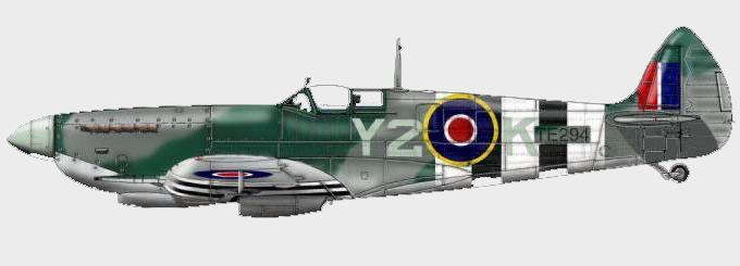
Y2-K Spitfire of F/Lt Arnold Roseland Spitfire HF Mk. IX, serial no. TE294 (restored), painted as LF Mk. IX MK304 Y2-K of No. 442 Squadron RCAF flown by F/Lt Arnold ...
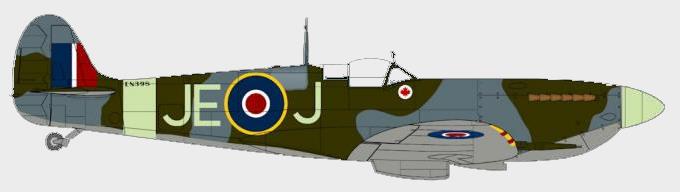
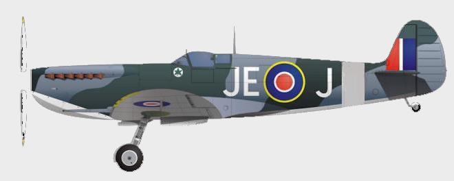
Johnnie Johnson’s Spitfire Revisited “I found the engineer officer and together we had a look at her, gleaming and bright in a new spring coat of camouflage paint.
Greycap’s Personal Spitfire On August 20th 1943, Canadians flying Spitfires arrived at Headcorn from Lashenden as their runway needed repairing.
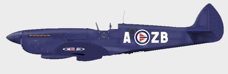
In Royal Norwegian Service Spitfire LF Mk. IXe, serial no. NH550, AH-Z “Kay” No. 332 Skvadron, Royal Norwegian Air Force, Bardufoss 1951 No. 332 (Norwegian) Squadron RAF
Reconnaissance Spitfires PR Mk. XI in Norway Supermarine Spitfire PR Mk. XI No. 1 Fotorekognoseringsving (photo-reconnaissance wing) Norway, 1950 In September 1946, UK Government agreed to supply Spitfires
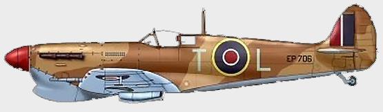
EP706, The Malta Defender Supermarine Spitfire Mk. Vb Sqn/Ldr Maurice Stephens No. 249 Squadron RAF Takali, Malta, October 1942
“Bogle” Bodie and his Spitfire Mk. I Supermarine Spitfire Mk. I P/O Crelin “Bogle” Bodie No. 66 Squadron RAF Click to enlarge image No. 66
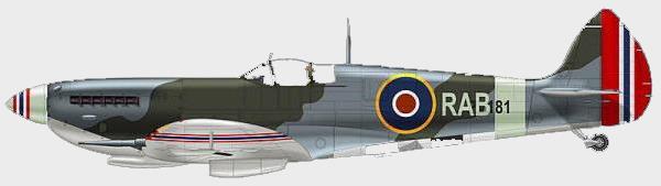
The Norwegian colours of Rolf Arne Berg W/Cdr Rolf Arne Berg was not only the CO of No. 132 Norwegian wing, but also one of the most dearly held officers